

HoverMix is a audio sampling controller designed to create a social experience when mixing music. Participants can work together to cue sounds and fade channels in and out similar to controls on a mixing board. However, unlike traditional mixing which is usually a one-man show, HoverMix is designed to be more enjoyable and spontaneous as more people participate. The experience can also be likened to a simpler form of DJing. With a few modifications from its current form, HoverMix could allow for a wide range of DJ-like interactions involving playback of sample libraries (i.e. live effects or remixing).
HOW IT WORKS – [VIDEO]
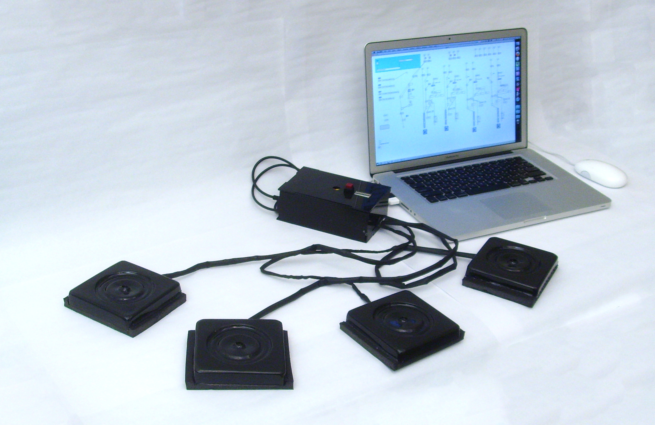
Users control the sound using one or both of their hands: when a hand is above a sensor, the assigned audio channel is activated and the corresponding musical sample begins playing in a loop. As the hand moves closer to the controller, the volume is increased. This allows users to fade in and fade out channels or to cut them in and out at full volume.
The Arduino controller in the base-unit receives input from the controllers through the implanted Infrared sensors (that judge distance from the surface to the hand). The Arduino constrains the information to numbers to represent gain data and also assigns a value based on whether the controller is activated (0 for off, 1 for on). The Arduino uses serial to send this information in a long string to MaxMSP. Thanks to the Arduino2MAX patch, MaxMSP can parse the data into separate values based on the order of the numbers. From there I used Max to assign the values to a gain meter and a play/stop command.
CONSTRUCTION
Materials
Computer:
MacBook running MaxMSP
Base-unit:
Arduino
Standard USB cable (included w/ Arduino unit)
Black Acrylic, 1/8″ thick
Female Headers – 24, joined
Controllers:
(material listed accounts for 1 controller)
- Infrared Sensor (I bought a couple of shorter range sensors, but the medium range had much better interaction.)
- Sensor Jumper Wire
- Wire
- 1kΩ resistor
- Headers x4
- Shrink tubing ~4ft.
- Black Foam Core square (approx. 4×5″, 1/2″ thick)
Vacuforming:
- Decorative wood block (found at Home Depot, sanded edges)
- Polystyrene Sheet (for vacuforming) x4
Making the Controller Casing:
This was my first time using Vacuforming. I had to find the right object to mold and found inspiration in a wood block I found at Home Depot. After sanding the edges, it was ready to form! Check out the video.

1. After vacuforming, I used an xacto knife to cut out the part I needed (very carefully!).
2. I drilled holes in the center for the IR light to pass through and I cut a port for the wires.
3. Then using standard black spray paint I painted the insides of the casing.


Making the Controllers:
1. Started by twisting three wires together, about 3′ long (color coded red, black, yellow.)
2. Soldered an IR sensor jumper onto one end.
3. Slid the wire into shrink tubing.
4. Soldered straight headers onto the other end. Used four headers, but pulled a pin out. The odd-one out is to make sure I plug the controller in correctly so the pins match up. I also used a small strip of electrical tape to secure the soldered ends.
5. Typically, heat is applied to the shrink tubing but I chose not to for time and aesthetics reasons.
6. After attaching the sensor I secured it to the foam-core base using some paperclips (cut and formed as staples) and hot glue.
7. I then cut grooves into the foam to help secure the outer casing.


8. Using hot glue, I secured the painted casing to the assembled foam base/sensor.


Making Base-unit:
The base unit has relatively simple construction. I began by using a laser cutter to create the box for the unit from the acrylic. (HoverMix Module casing PDF) In the original design I included holes for a potentiometer, pushbutton, and bar graph LED. However, these elements were not functions in my final version.
I soldered 18 wires onto a strip of 24 female headers to match the connections on the controllers – 6 controllers can connect to the system at one time. I then inserted this wire assembly into the outer casing. The cut of the acrylic was so close that I did not need to add any additional adhesive. However, I added a little glue later on after I found the controller connections could loosen and were difficult to push back in.


I then put the box together piece by piece and using crazy glue to secure each side.
DIAGRAMS
Wiring Diagram:

‘Fritzing’ Diagram shows the physical connections:

CODE
Arduino Code (via Pastebin)
MaxMSP Patch (see image, adapted from Arduino2MAX):

EDITING SOUND SAMPLES
Editing the samples was relatively easy. Any basic audio software could be used to trim the audio, but I chose RogueAmoeba’s Fission because it handles splicing of audio tracks fairly easily without losing audio quality.

My demo samples were taken from a new track called “Derezzed” from Daft Punk’s Tron Legacy soundtrack (link to music video). However, any set of audio samples that can be looped without a gap in playback would work appropriately. Ideally, all samples would have the same tempo. (Download/listen to samples here.)
PROCESS
The exploration of Arduino’s capabilities in sound took much more time than I expected but I am pleased with the result. To generate sound form the Arduino, I explored tone generation, MIDI, and sound sampling.
I found that concurrency became the greatest issue keeping me from using the simplest solutions. Since I originally looked into music composition, part of my exploration included raw wave generation from Arduino or Processing. However, combining wave sounds (from multiple controllers) is much more difficult from the software side and really wasn’t achieving the affect I was going for regardless of trying to use tone libraries (resources: Tone Library, Minim, Sonia).
I made multiple attempts trying to produce MIDI from my Arduino using serial commands in MIDI language. I looked to the ardrumo project for inspiration, but couldn’t really utilize any of the features for my own project. To generate MIDI signals I needed to have a program to convert the serial data into MIDI and send to virtual MIDI ports on my computer. My major issue was getting the virtual ports recognized by other software in order to use the MIDI data produced. Midi communication would allow the most versatile control of audio, controlling tone, sound dynamics, or being mapped to controls like play/pause/fast forward (resources: MMJ, Midibus, IPmidi, Serial Midi Converter)
Finally I looked at other software to help me out. I had looked before at a wave shield kit to attach a speaker and memory card to play samples, but again this solution does not allow for processing of multiple channels of audio data. In the end I found MaxMSP to offer a logical programming interface (with lots of documentation!) and I used the Arduino2MAX patch to get the arduino talking to my computer.
